Page 1 of 1
switch and ammeter wiring
Posted: Tue Jun 27, 2023 9:31 pm
by makenstuff
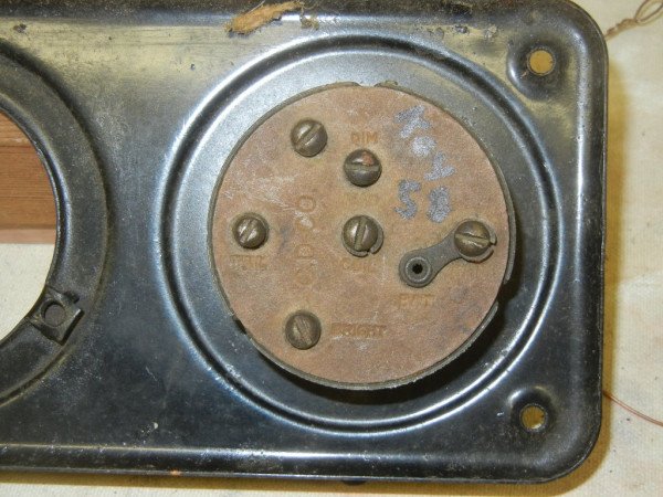
I'm preparing to rewire this 26 TT. The existing wiring is a bit of a conundrum. Let's start with the ammeter to switch panel. all the diagrams I've seen have the battery wire directly to the ammeter, then jumped to the switch, then back out to the car. (Solid Yellow to ammeter, Yellow black jumper to switch, Yellow black to wiring block on firewall). The existing wire has the jumper from ammeter to switch, but both hot wires directly to one side of the ammeter. The post looks to be designed for this purpose. Should I rewire per all of the diagrams and ignore this anomaly?
Re: switch and ammeter wiring
Posted: Tue Jun 27, 2023 10:02 pm
by TRDxB2
If you get a repro wire harness it may force you to wire in the normal,position because of the wire length. But your current wiring - makes no difference which end of the "jumper wire" you connect to.
Re: switch and ammeter wiring
Posted: Tue Jun 27, 2023 10:11 pm
by John kuehn
Some of the new repo wiring sets may have slightly different color wires than the original wiring so be sure to use the correct wiring diagram when you’re rewiring your car.
Hopefully the new repos are now pretty much correct as one I used wasn’t exactly all correct as far as the color went. It came down to following a diagram to get it right by the process of elimination as the different colored wire was the only one that would be correct for the terminal screw.
Re: switch and ammeter wiring
Posted: Tue Jun 27, 2023 10:52 pm
by makenstuff
Thanks. So to be clear, on my existing ammeter, on one post, (the left post in the rotated photo), the ammeter is connected to the switch and the generator, the other post is connected to the battery.
My new harness is color coded like this. So, I'll just rewire to match these diagrams.
Re: switch and ammeter wiring
Posted: Tue Jun 27, 2023 11:36 pm
by Steve Jelf
This shows correct wiring, colors, and wire sizes.
Re: switch and ammeter wiring
Posted: Wed Jun 28, 2023 10:07 am
by Oldav8tor
There is a difference between the photo and the diagram. In the Photo, the "bright" headlight wire goes to 5 on the terminal strip and the "Dim" to 6. On the diagram those two wires are reversed. Not a big deal but confusing.
This drawing appears to be old but I don't know it's source. It shows the "Bright" on 6 and "dim" on 5 like in Ron's drawing. Either way you'd be OK as long as you followed thru with connecting the switch Bright/Dim to the same posts as the headlight's Bright / Dim.
Re: switch and ammeter wiring
Posted: Wed Jun 28, 2023 10:33 am
by Been Here Before
- DSCN1620.JPG (72.15 KiB) Viewed 1667 times
Re: switch and ammeter wiring
Posted: Wed Jun 28, 2023 11:12 am
by Jerry VanOoteghem
Your current wiring is a mess. I would completely remove it and ignore everything about it. Install the new harness according to the wiring diagrams posted above. To do any less, would be repeating past errors and "work arounds". Also, forgive me if you already know this, but T's have a negative ground. I only mention it because maybe the person who installed your current wiring may not have known it.
Re: switch and ammeter wiring
Posted: Wed Jun 28, 2023 11:36 am
by DHort
www.texastparts.com
Go to free downloads
Print out your wiring diagram from there
Same as what Steve shows above
Re: switch and ammeter wiring
Posted: Wed Jun 28, 2023 12:04 pm
by makenstuff
Jerry VanOoteghem wrote: ↑Wed Jun 28, 2023 11:12 am
Your current wiring is a mess. I would completely remove it and ignore everything about it. Install the new harness according to the wiring diagrams posted above. To do any less, would be repeating past errors and "work arounds". Also, forgive me if you already know this, but T's have a negative ground. I only mention it because maybe the person who installed your current wiring may not have known it.
That is the plan. Right now, the car runs and drives on battery only. I don't know if the magneto works. The lights don't work. The windshield wiper does though

The current wiring has so many splices, frayed spots, and colors, that replacing it seemed like the best place to start. Considering that it runs, my only hesitation is that it won't after I rewire it. It looks fairly simple. I just balked when I saw more wires coming from the ammeter than any diagram that I had seen.
Thanks for everyone's help!
Re: switch and ammeter wiring
Posted: Wed Jun 28, 2023 1:31 pm
by TRDxB2