Page 1 of 1
Wiring of “early two piece” timers
Posted: Thu May 23, 2019 11:58 pm
by TonyB
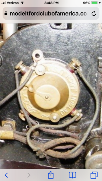
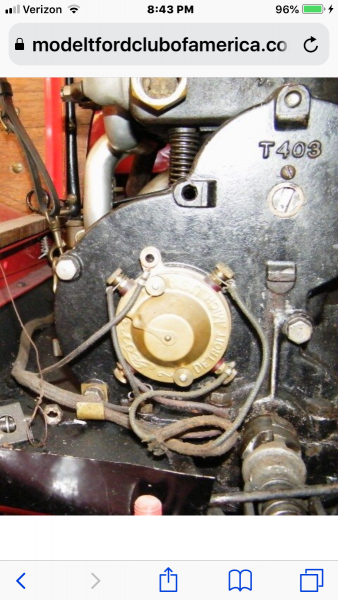
There is another thread showing a magnificent drawing of the early (up to 2500) fan assembly. In the discussion there is a picture of an actual car, seemingly #371, and it shows the wiring of the two piece timer. It appears to use a wire loom and shows a fifth wire which appears to be a ground return.
I thought the loom was actually four individual wires in a casing with rubber ends.
I have never previously seen a fifth wire as a ground return. Where does it connect on the coil box?
Anyone any comments.
Anyone know what is “correct”?
Re: Wiring of “early two piece” timers
Posted: Fri May 24, 2019 12:35 am
by TonyB
I forgot to include the picture

- 5 wires on two piece timer

- Wire loom on two piece timer
Re: Wiring of “early two piece” timers
Posted: Fri May 24, 2019 3:04 am
by Wayne Sheldon
I do not know! However, to me, that looks like the standard timer wiring loom including the wire for the generator. In the past, some looms suffered availability issues. As I recall, some reproduction generator era looms were sold without right headlamp wire. Of course, we cannot see in the photo if that loom has the headlamp wire or not.
My guess, and this is wholly a guess, someone used a loom with a generator wire and no generator. So they simply put the extra wire on the two-piece timer thumb nut. And? Maybe they thought an extra grounding might help?
Re: Wiring of “early two piece” timers
Posted: Fri May 24, 2019 9:36 am
by Scott_Conger
Wayne
I'm with you on this
Re: Wiring of “early two piece” timers
Posted: Sat May 25, 2019 4:24 pm
by TonyB
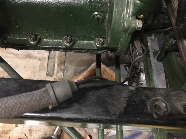
I took a photo of the loom on my 09, it is basically four wires inserted into a cable housing with a rubber end.

- Timer end of wire loom
On looking more closely at the loom on #371, I believe it is a “generator” loom, with the generator wire used as a ground wire.