Page 1 of 1
Moving the Screw on the back of a 1915 headlight
Posted: Mon Nov 04, 2024 11:32 am
by moozark
Quick question: what are the differences between 1915-16 headlight and the later lights? I've noticed that the position of the screw is on top. Can a later headlight be converted to a 1915 style by rotating the light bulb socket, so that the screw is on top? I need a pair of 1915-16 lights but I only have one with the screw on top. Why did they change the position of the screw anyway?
Re: Moving the Screw on the back of a 1915 headlight
Posted: Mon Nov 04, 2024 12:00 pm
by DanTreace
Those early lamps used a single filament bulb, so the collar in the hole has adjusting slot positioned for the screw drive adjuster of the bulb socket. Later lamps use the Tu_lite bulbs, with dim and high beam filaments, so the side screw type housing came about.
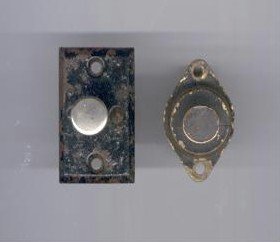
Early lamp
Early lamp housing
Later lamp , note the slot for the adjusting tab on the bulb socket, that slot has to be oriented to the tab of the bulb socket
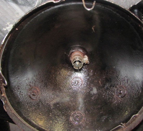
- IMG_2002 (640x584) (560x511) (550x502).jpg (135.74 KiB) Viewed 1695 times
The collar fitted to the bucket is sort of pinned or pinched, it determines the position of the lamp socket. That collar has cutaway for the action of the socket going in and out to adjust the beams.
IMO, would try to find a matching set of buckets, they are available from 1915 to 1920 or so.
Re: Moving the Screw on the back of a 1915 headlight
Posted: Mon Nov 04, 2024 12:03 pm
by Steve Jelf
It's been a long time since I studied this, but I believe the 15-16 headlights are unique. Changes like this were made when the engineers figured out something that would work better or cost less.
Re: Moving the Screw on the back of a 1915 headlight
Posted: Mon Nov 04, 2024 12:46 pm
by Dan Hatch
Rick send me an email. I may still have one Dan
Re: Moving the Screw on the back of a 1915 headlight
Posted: Mon Nov 04, 2024 1:18 pm
by TRDxB2
There is another other subtle difference that has done unnoticed. An original double filament 6V bulb has two "A" shaped filament such that the pins in the body would cause these to be oriented horizontally when inserted into the headlight socket. This configuration is a BA15D (BAY15D has two offset pins).
--
I have two different double contact sockets, such that the orientation MAY be compatible with the different position of the headlight adjusting screw location. I came across the difference in cleaning up a bunch of sockets. I just came across some 1915 headlights that I have yet to take apart to confirm a difference,
--
As you can see the two different adjusting screw positions result in their contacts being in a vertical position. So moving the screw may require a different socket if the headlights can't be focused correctly.
There were some 1915 headlights in my Barn Find. I will need to take them apart to see what sockets are being used.
Re: Moving the Screw on the back of a 1915 headlight
Posted: Mon Nov 04, 2024 3:16 pm
by Steve Jelf
As originally designed, mag lights have no provision for high or low beams. They are either on or off. Bulbs actually made for the purpose are pretty scarce, but fortunately there are others that will serve well enough. Ford abandoned mag lights for good reason. Trying to go fast enough to make them show you the way, you will outrun them. I have driven to town to watch the fireworks, and a city or town is so well lit that it's not too bad. But an unfamiliar road on a dark night? Not me.
Re: Moving the Screw on the back of a 1915 headlight
Posted: Mon Nov 04, 2024 4:17 pm
by Erik Johnson
The adjustment screw was at the 12 o'clock through at least the 1917 model year and the headlamps are not as scarce as one might think.
If you are stickler, you should have a matched pair made by the same manufacturer. For example, the headlamps on my unrestored May 1917 roadster are John Brown while the headlamps on my father's July 1917 touring are E&J.
The headlamps with the adjustment screw at the 9 o'clock position may have been adopted early in the 1918 model year in conjunction with the change to the combination horn button/light switch-dimmer which I believe was around October 1917 based on some posts by John Regan and a surviving, early 1918 touring which still had the light switch on the firewall.
Re: Moving the Screw on the back of a 1915 headlight
Posted: Tue Nov 05, 2024 3:24 pm
by KWTownsend
For 1915, 1916, and into 1917, the headlight focus screw is at the 12 o'clock position:
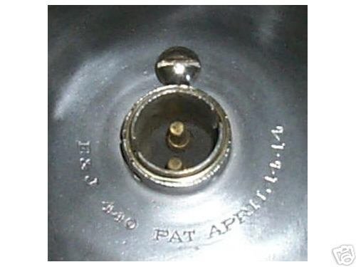
- 1915 headlight E&J model 440.jpg (22.95 KiB) Viewed 1499 times
Notice the contacts are in line with the focusing screw.
If right angle headlight connectors are used and the wrong sockets are used, the right angle headlight connector will sit 90° off
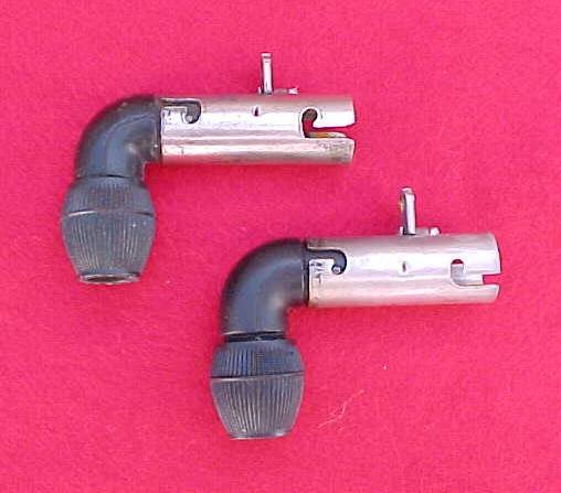
- 1915 headlight sockets & plugs.jpg (30.89 KiB) Viewed 1499 times
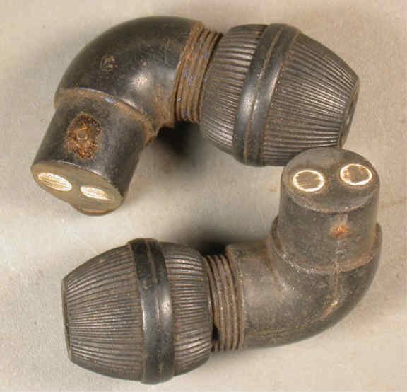
- 1915 headight plugs.jpg (30.46 KiB) Viewed 1499 times
These used a push-pull headlight switch. The rectangular switch is "pull on, push off" the round switch is "push on, pull off."
- 1915 headlight switches 2.JPG (15.9 KiB) Viewed 1499 times
Late in 1917, the combination horn and headlight switch was introduced. The headlight switch as three positions: Off, On, and Dim. A resistance unit was mounted on the firewall. The theory was when driving at high engine RMS, turn the headlights to the resistance unit position to help keep the light bulbs from burning out.
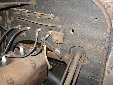
- headlight dimmer unit.jpg (45.2 KiB) Viewed 1499 times
: ^ )
Keith
Re: Moving the Screw on the back of a 1915 headlight
Posted: Tue Nov 05, 2024 4:26 pm
by Erik Johnson
The adjustment screw was at the 12 o'clock position through at least the 1917 model year.
The combination horn button/light switch and dimmer coil on the firewall was introduced early in the 1918 model year (the fall of 1917).
Re: Moving the Screw on the back of a 1915 headlight
Posted: Tue Nov 05, 2024 5:04 pm
by KWTownsend
Erik,
Thank you. Corrected.
Here is a wiring diagram for the resistance unit:
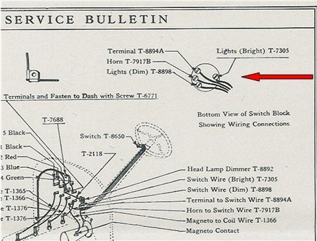
- headlight horn wiring.jpg (46.58 KiB) Viewed 1466 times
How long were the right angle headlight connectors used?
Were they on Rip Van Winkle?
: ^ )