Page 1 of 1
solenoid wiring question
Posted: Tue May 20, 2025 12:01 am
by KWTownsend
I should stick to stemwinders. But I am not...
I don't like the location of the original starter button, so I am wiring a solenoid in my wife's 6v speedster (negative ground) and have found two vastly different wiring diagrams:
This diagram makes sense to me. The solenoid takes the place of the original button and a new button sends a signal to make the connection inside the solenoid. It shows 6v+ going to the small connection via the starter button.
This diagram says it is for 6v system
I am using 6 volts. But the wiring is very different. This one show Ground going to the small connection via the starter button.
Why would the wiring be different just because the voltage is different?
Please help we wrap my head around this.
: ^ (
Re: solenoid wiring question
Posted: Tue May 20, 2025 1:09 am
by Craig Leach
Solenoids are not all the same! if it has one small terminal then it is most likely internally grounded. If it has two small terminals one marked s
& one not marked then the unmarked one is a ground. If it has two small terminals one marked s & one marked i the i goes to the coil to to
supply full volts to the coil bypassing the ballast resistor when cranking. ( I have run into one that the i terminal was the ground) Many 12vdc will
work on 6 volts.
Craig.
Re: solenoid wiring question
Posted: Tue May 20, 2025 11:50 am
by mbowen
Keith, the second diagram you posted appears to show a solenoid type common in aircraft “master” relays, and sometimes starter solenoids. One side of the coil is is internally connected to the battery side of the main contact, and the other side of the coil goes to a simple on-off switch in the case of a “master” solenoid, or a momentary push button in the case of a starter solenoid. The switch merely provides a ground to complete the coil circuit. The intent is to keep all “hot” bus voltage out of the cockpit until the master is turned on,
Re: solenoid wiring question
Posted: Wed May 21, 2025 10:57 am
by Mark Gregush
The Ford style one I am putting on, the style with the push button on the bottom (like the Texas T diagram), the terminal that goes to the switch: The wire goes from the terminal to the switch, the other side of the switch is grounded to the chassis. I am adding a keyed lock on the grounded side. Be sure to connect the battery cable to the correct side of the solenoid!

Re: solenoid wiring question
Posted: Wed May 21, 2025 2:43 pm
by browning
There are at least three different solenoid types, regardless of voltage, based on their internal wiring. They look almost identical and are easily confused. The first has the solenoid coil connected internally to the “battery” post and has a small stud for the trigger which will energize the coil when grounded through a switch. The second is exactly the same except that the coil is connected to the chassis ground internally and is energized when the small trigger post is connected to the voltage source, again through a switch. The third has the coil isolated internally and has two small posts which require connection with both ground and voltage. The manufacturer may or may not construct them with a manual button built into the solenoid. They are also produced for either intermittent or continuous operation either of which will work for the purpose of operating a starter.
Re: solenoid wiring question
Posted: Wed May 21, 2025 3:54 pm
by KWTownsend
I will try this solenoid:
Wired with the second diagram.
Re: solenoid wiring question
Posted: Wed May 21, 2025 4:02 pm
by A Whiteman
Hi Keith,
You have stirred me up!
My Colonial Roadster starter button is difficult to use, and I have pondered putting a solenoid in with a button on the dash (a suitably 'vintage' button!), so your post has spurred me on to make the install. Good prompting and good discussion to help me along

Kind regards
Adrian
Re: solenoid wiring question
Posted: Wed May 21, 2025 8:11 pm
by Dollisdad
I use the same solenoid mounted inside the frame with a starter button out the bottom of the coil box.
Re: solenoid wiring question
Posted: Thu May 22, 2025 12:01 am
by KWTownsend
Tom,
6v?
Wired so the small contact goes to one contact on the starter button and the other side of be starter button contact to ground?
Keith
Re: solenoid wiring question
Posted: Thu May 22, 2025 2:09 am
by BE_ZERO_BE
Keith,
When I put a starter on mt '16 I used a three terminal solenoid.
The solenoid had one of the large terminals marked "BAT".
Below is the diagram of the solenoid that I used.
As you can see, the coil is internally connected to the "BAT" terminal.
The small terminal needs a ground to activate the solenoid.
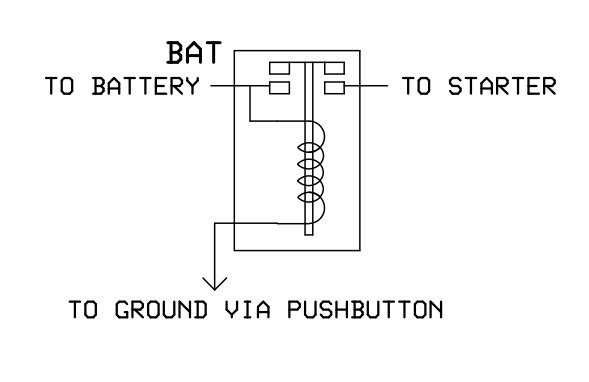
- SOLONOID.jpg (15.64 KiB) Viewed 2834 times
Re: solenoid wiring question
Posted: Thu May 22, 2025 11:05 am
by Dollisdad
Here is the wiring diagram I use. I don’t think it makes a difference if it’s 6V, except solenoid and battery.
Re: solenoid wiring question
Posted: Thu May 22, 2025 11:20 am
by Dollisdad
Using the hand brake bolts as an attachment location, I remove the paint between the bolts so the solenoid grounds to the frame. The mounting holes in the solenoid will have to be enlarged to accept the hand brake pattern.
Re: solenoid wiring question
Posted: Thu May 22, 2025 12:50 pm
by TRDxB2
There are different types of solenoids based of use: Continuous, Intermittent & Marine. The intermittent (Ford style) is for automotive use.
Irrespective of voltage there are 3 pole & 4 pole configurations. Each of these is wired differently for a starter button (there are some other dependencies we don't care about) . The initial diagrams above are correct for each of these type but not labeled as such. HOWEVER, the TEXAS T instructions confuse the issue in showing just an
S pole on the wrong side of the unit while the photo in the catalogue shows a 4 pole solenoid.
--
So what type of solenoid are they selling, 3 o4 4 pole?
--
--
--
--
So for a 4 pole solenoid
--
--
--
For a 3 pole solenoid
--
Re: solenoid wiring question
Posted: Thu May 22, 2025 1:57 pm
by ewdysar
Good info, Frank.
I have a 4 pole solenoid mounted on the bottom of the frame rail in my '14. I have the start button on the bottom of the coil box where I can hit it with the tip of my shoe, very handy if the engine stalls at a traffic signal. Because I'm using the regular T ignition with coils, timer and mag, the "I" terminal is not in use.
The noticeable difference between the 3 pole and 4 pole solenoid schematics is that with the Texas T 3 pole diagram, the switch/button circuit appears to provide intermittent ground to the "hot" S terminal. With the 4 pole diagram, and in my car, the "hot" switch/button circuit provides the S terminal with intermittent voltage. My installation has been working fine for 10 years.
That said, this was put into the car to be reversible, with as few new holes as possible. It will all come out when I put the original '14 stemwinder back into the car.
Keep crankin' (or maybe not, if you're using a starter)

Eric
Re: solenoid wiring question
Posted: Thu May 22, 2025 2:52 pm
by Mark Gregush
I am mounting mine on the old starter switch mount and the momentary contact switch will be on the firewall.