Page 1 of 1
HELP!!!!!!!!!
Posted: Sat Jul 27, 2019 12:02 am
by Paul B
I KNOW THERE MUST AN AGGREGATE NORTH OH 25000 YEARS OF COMBINED MODEL T EXPERIENCE OUT THERE., SO IM' SURE SOMEBODY CAN HELP ME ON THIS.
I WANT TO PUT STOP TURN & RUNNING LITES ON MY T. SO I BOUGHT THE FRED HOUSTON MTFCA "T" TIPS CD 7-4 MODEL T SAFETY PART 1. THEN I BOUGHT THE LED LITES, THE TURN SWITCH THE BBAKE LITE SWITCH & BLINKER RELAY. IT LOOKED SO SIMPLE IN THE VIDEO, I SAID "WHAT COUILD GO WRONG?" WELL YOU NEED A CIRCUIT DIAGRAM WHICH IS NOT IN THE VIDEO. THAT'S WHERE THE TROUBLE STARTED; THE LED LIGHTS HE RERCOMMENDED HAD TWO FUNCTIONS, BRIGHT & DIM. THE CAR NEEDS THREE FUNCTIONS; RUNNING, STOP, & TURN. I HAVE BEEN PLAYING ON A "BREADBOARD" WITH ALL THE COMPONENTS MOUNTED, A 12 POWER SUPPLY. & A BUNCH OF CLIP LEADS. THE BEST I CAN DO IS GET RUNNING LIGHTS & TURN SIGNALS, WHEN I HIT THE BRAKE SWITCH THE TURN SIGNALS GO OFF & THE LIGHTS STAY SOLID BRIGHT. IF ANY ONE CAN GIVE ME A CIRCUIT DIAGRAM THAT WILL GIVE ME THE THREE FUNCTIONS I WILL BE VERY GRATEFUL
ALSO IF I COULD BUY NEW RED LED LIGHTS WITH THREE FUNCTIONS I WOULD DO IT.
THANKS FOR READING THIS, PAUL
Re: HELP!!!!!!!!!
Posted: Sat Jul 27, 2019 12:45 am
by Scottio
I am unfamiliar with the system that you have but you need either an integrated turn signal switch that will integrate turn and brake lights or, as you said, three lights in back. One dual filament and another single filament.
Re: HELP!!!!!!!!!
Posted: Sat Jul 27, 2019 6:29 am
by It's Bill
It would be great if someone who has accomplished this feat of electrical engineering could publish a list of components that will work correctly together along with a circuit diagram used to hook them together. I have followed diagrams published before, which look logical and easy enough, but have not been able to get a working system using led lights. I have heard time and again that led lights are finicky, but there must be a combination that will work! Cheers, Bill
Re: HELP!!!!!!!!!
Posted: Sat Jul 27, 2019 7:36 am
by Charlie B in N.J.
the function you're looking for is in the proper type turn signal switch. for instance; you're stopped at a light with the left turn signal on. the switch allows the right brake light to be on but removes the left from the brake circuit and routes it through the turn signal flasher so you have 1 turn signal light & 1 brake light. The system uses the same filaments (bright) in the bulbs. obviously the opposite happens with a rt. turn signal situation. It's all in the switch.
Re: HELP!!!!!!!!!
Posted: Sat Jul 27, 2019 8:21 am
by TWrenn
The signal system that Charlie mentions above is readily available from the vendors. They even have the diagram you need. I put a set on my 25 with no problem. You can either supply your own wiring as I did, or pony up about $90 and get the "ready made" set for it to make things simpler. I pulled the Jelf Mr. Thrifty card and ran all my own scrap wiring that someone gave me for free. It seemed to make the signals work better!

Re: HELP!!!!!!!!!
Posted: Sat Jul 27, 2019 8:31 am
by dhosh
I didn't purchase a kit.... But did put in drop resistors (mounted on the firewall), as the LEDS didn't pull enough current to get the lamps to flash.
As it sounds like you have the blinkers working on your breadboard, this likely isn't your problem, however.
Re: HELP!!!!!!!!!
Posted: Sat Jul 27, 2019 9:02 am
by Allan
I once tried to set up LED running lights. Gave up on it and ran globes with standard filaments. These are much easier to adapt to existing lights or period additional lights. They require no additional resistors, no special flasher can or switch and most importantly, no new tricks for me to learn. Besides which, I can do it my way with 6 volt components.
I am told LEDS have NO filaments. The same LED is driven in different ways to achieve brighter brake lights. How this happens will remain a mystery to me.
Allan from down under.
Re: HELP!!!!!!!!!
Posted: Sat Jul 27, 2019 9:40 am
by mtntee20
Paul,
Sorry, I could not find the supplier. We bought them off of tbay. I just looked there and you can find any color or configuration of the bulb you would like. We purchased a standard aftermarket 7 wire turn signal switch. You will need an electronic flasher as the LED bulbs will not draw enough current to make a standard flasher work. I plan on hiding the switch under the dash so it will be much less visible with only the handle protruding just enough to use. I have set up this system in the past and it has worked very well for me, just follow the 7 wire diagram for your switch.
Good Luck,
Terry
Re: HELP!!!!!!!!!
Posted: Sat Jul 27, 2019 2:02 pm
by TRDxB2
It would help to see what the components you have are and/or how you have things wired now. I assume that the taillights are double contacts.The first diagram is the general wiring using a black box (trailer), second diagram, that takes care of making the tail light brighter when you step on the brake. You may not need this - don't know what you have. The last one is for '26 T. If you show me what you have I can help.
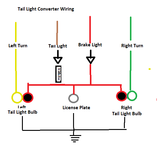
- Taillight Converter Box.png (9.63 KiB) Viewed 8252 times
- 1926-1927-model-t-ford-wiring-diagram-p1.gif (35.77 KiB) Viewed 8252 times
Also your flasher needs to be for LED lights. Suggest you work on the turn and brake lights first then the turn signals. LOL Frank
Re: HELP!!!!!!!!!
Posted: Sat Jul 27, 2019 3:36 pm
by TRDxB2
I meant to say work on the tail & brake lights first - everything else disconnected
Re: HELP!!!!!!!!!
Posted: Sun Jul 28, 2019 1:45 am
by Paul B
I REALLY AM GRATEFUL TO ALL MY FELLOW T LOVERS WHO RESPONDED TO MY REQUEST. I AM GOING TO SEE WHAT I CAN DO WITH ALL THE INFO YOU GAVE ME & REPORT BACK LATER. REGARDS, PAUL
Re: HELP!!!!!!!!!
Posted: Sun Jul 28, 2019 11:32 am
by MrTwT1915
Gentlemen
First you do not have to use a load resistor when using LED lights. Just buy an electronic flasher, these are designed to work with LED Lights & NO LOAD RESISTOR required.
I recently spent a lot of time writing an article for the Vintage Ford magazine explaining how to use LED lights on your Model T complete with a wiring diagram & parts list.
If you go to my website
www.twcomponents.com you can download the article from the Tech Articles tab.
If anyone has any questions just call me or send me an email.
Re: HELP!!!!!!!!!
Posted: Thu Jul 30, 2020 9:39 pm
by Jerry Young
What is the part number of the trailer converter in the above diagram and will it work on 6 volts?
Thanks
Jerry
Re: HELP!!!!!!!!!
Posted: Fri Jul 31, 2020 8:31 am
by GrandpaFord
I am not sure if this will help because I think I have a different turn indicator switch, but in order for my rear lights to work correctly, i.e. one light blinking and the other solid when turning and braking, I had to wire the brake lights through the turn indicator. There was one wire coming from the turn indicator that got power from the brake light switch. The current ran from the brake light switch to the turn indicator and then to the brake and turn indicator lights. That way the turn indicator switch was controlling both the brake and turn indicator functions. Hope this is clear enough.
Re: HELP!!!!!!!!!
Posted: Fri Jul 31, 2020 9:59 am
by Mark Nunn
Jerry Young wrote: ↑Thu Jul 30, 2020 9:39 pm
What is the part number of the trailer converter in the above diagram and will it work on 6 volts?
Thanks
Jerry
I don't have a part number since I bought a kit from one of the vendors. But, go to etrailer.com and search for a universal converter, not a model-specific converter. They have the 4-in, 3-out converters that don't require a 12V power wire.